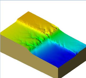
WILSIM is a Web-based Interactive Landform SIMulator. It was created as an educational tool, to demonstrate how the processes of erosion, climate, and tectonics produce landforms found in nature.
An in-depth description of the WILSIM program and its use can be found on the WILSIM Home Page.
The purpose of these pages is to describe some of the technical underpinnings of WILSIM.
Design Goals
Some principle WILSIM design goals were- Ease of use.
- Ease of installation.
- Simulation visualization
Java applet
The ease-of-use goal led us to adopt a Java applet for the final product. Users can run the progam directly from their web browser. We strongly considered the advantages of a Java application, namely the ability to store intermediate results to disk, but we felt that the need for signed authorization certificates would reduce the ease of use.
The goal of ease-of-installation strengthens the case for implementing a Java applet. The platform independence of Java eliminates the need to produce different executables for different platforms. Nor do users need to know enough details of their machines to select the proper executable.
Implementing the simulator as an applet lets users run the program on machines where they may not have sufficient privileges to install a stand-alone program. Such is frequently the case in university computer labs and libraries.
No Java 2.0 or Java 3D
Ease of installation also led us to the stricter requirement of not depending on third-party plugins or libraries. At the time (2002), this meant not using Java 2.0 or Java 3D as these were typically not installed by default on most machines. This meant that we needed to write a custom 3D rendering engine for our project using Java 1.1
Visualization Goals
The visualization goals of the WILSIM project were- The terrain grid should be rendered in 3D.
- The grid should be seen as solid.
- If possible, simple lighting effects should be used to enhance the realism of the visualization.
- If possible, the visualization should be done at interactive rates.
WILSIM Architecture
WILSIM consists of three basic sections: the simulation, the visualization, and the user interface. Each section also has a separate thread of control.Simulation section
The simulation thread changes the terrain grid according to established algorithms. More details about the simulation algorithm can be found on the WILSIM site. In brief, one step of the iterative algorithm traces the path of a single "precipiton" as it starts at a random point on the grid and moves downward, eroding the terrain as it goes. Tectonic uplift is applied at each step and climate parameters are changed as needed.
Whenever the height of a particular grid point changes, the change is registered with the visualization section. For interactivity, the simulation thread relinquishes control after processing a single step of the simulation.
Visualization section
The visualization section maintains a copy of the terrain height values and the color for each grid point. The rendering engine uses double buffering. The grid is rendered to an offscreen buffer. When the rendering is finished, the buffer is copied to the screen.
A naive approach would redraw the terrain for every change made to the grid. This would lead to very slow simulation in exchange for prompt visual fidelity which is difficult to notice in this application.
In the implemented approach, the rendering thread reliquishes control after drawing a single row of the grid samples. Many grid values can change between activations of the rendering thread. This simply means that a single rendering pass through the grid will reflect the cumulative changes. It's possible to send an image to the screen that does not accurately reflect the true state of the grid, but since the grid is drawn relatively quickly, this problem has not been noticed in practice.
User interface section
The user interface section handles the input of all parameters governing the simulation. It was redesigned extensively during the implementation to present only a minimal amount of information to the user at any given time. This leaves more screen real estate for the visualization.
For the sake of perceived interactivity, the user interface thread is given a higher priority than the threads associated with simulation or visualization. Most of the time, this thread is inactive.
Rendering Engine Design
Even though the decision to write a custom rendering engine was based on a design goal for ease of installation, it turned out that writing such an engine let us introduce specific speedups customized to the application at hand. This section gives the details behind the rendering engine.
A standard general purpose rendering engine takes all of the polygons in the scene to be rendered and transforms them into screen coordinates. The resulting screen polygons are scan converted into pixels and drawn using colors computed in lighting calculations. The transformation process is often split up into multiple transformations so that lighting calculations and clipping against screen boundaries can be performed at the proper stages.
The Java 2D drawing libraries contain the ability to draw arbitrary 2D polygons. This would seem to obviate the need for a custom scan conversion routine. But the Java routines require integer valued coordinates. With large, dynamic collections of small polygons, such as those in the terrain grid, integer valued polygons suffer from sampling effects that make the collection appear to shimmer. Given this effect, we felt it worthwhile to implement proper polygon scan conversion routines as well as transformation and lighting routines
Rendering Pipeline Simplification
A traditional general purpose graphics pipeline transforms scene points to screen points by passing them through a 4 by 4 transformation matrix. This involves 16 multiplications, 12 additions, and an eventual 3 divisions for every transformed point.
We realized that in our application we wouldn't need closeup views of the terrain. This meant that perspective foreshortening effects would be very minimal. So we eliminated perspective projection entirely and went with the mathematically simpler orthographic projection.
We also noticed that carefully choosing the rendering order made it possible to eliminate the need for pixel depth in screen coordinates. Consequently, the final cost for transforming any point in the grid was reduced to 6 multiplies, 9 additions and no divisions.
In the interior of the grid, each grid point represents a corner of four quadrilaterals in the visualization. Rather than transform the same point four times, the proper rendering order also made it possible to easily save the transformed values for reuse in subsequent calculations.
Depth Simplification
A general purpose scan conversion rendering engine often makes use of a depth buffer to hold the depth of every point in the image. As new objects are drawn in arbitrary order, the depth of the pixels to be drawn is compared with the depth of the points already in the image. The color and depth of the closest points prevail, making objects look solid.
Even though they have arbitrary height, the polygons of the terrain still come from an underlying rectangular grid. This makes it advantageous to use a technique known as the painter's algorithm. With a little analysis we can find which corner of the grid is farthest from the viewer. The polygons of the grid are then drawn from the farthest grid corner to the closest. No depth comparisons at all are needed in the drawing.
Lighting Simplification
A Lambertian lighting scheme computes the intensity of light reflected off of a surface to be proportional to the dot product of the surface normal (N) and the direction to the light source (L). By making the light direction a carefully chosen constant direction (0, 1, 1), the dot product calculation is reduced from 3 multiplications and 2 additions to a single addition.
In practice this does not provide a significant speedup. The color of each grid quadrilateral is constant for all of its pixels. So the lighting calculation only need be done once for each quadrilateral, a small number compared to the other calulations going on. But because it was trivial to implement, we added the speedup to WILSIM.